A Beginners Tutorial to Data Telecommunications Concepts
Lesson 101


| Before starting the lesson, please take a moment to familiarize yourself with some of the terms and the graphical symbols that will be used to represent them. |

|
These first desktop devices used by people (referred to as users) become widely accepted as CRT's, though this name did not adequately describe their true nature. Actually these devices were terminals attached to a mainframe computer system. A terminal is an end device where the computer system and humans interact. Our discussion will be limited to the CRT, thought there are many other types of terminals.
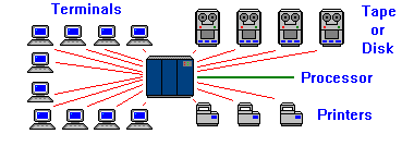 |
Mainframe is a name used to describe a computer system that is not self-contained. Most mainframes will have a large processing unit (usually larger than an average automobile) , several storage devices (tape or disk), and a series of terminal devices. For the sake of simplicity, we will not include the external devices in future diagrams
|
Since these CRT terminals connected to the mainframe have no processing power of their own, they are called dumb terminals. If the mainframe is switched off, the dumb terminal is not able to function. In most cases, if the mainframe crashes, the dumb terminal will display the last screen of data it received until the mainframe recovers. Once available, the mainframe will place the dumb terminal back to its starting point, thus loosing what ever data was displayed on the screen.
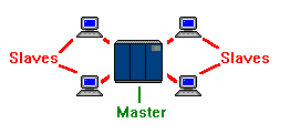
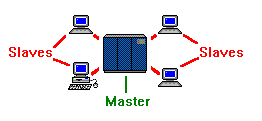
This relationship between the mainframe and the dumb terminal is referred to as a master-slave relationship. The mainframe represents the master, and the dumb terminal represents the slave. The slave is unable to execute any actions on its
own; it can only do what it is permitted to do by the master. Some would argue that when a command is issued from a dumb terminal (slave) that is directing the mainframe (master). This is a fallacy, as the dumb terminal is only allowed to issue the command because the mainframe has given it the authority to do so.
|
Our first diagram shows the master-slave relationship of dumb terminals to their mainframe. It is important to understand that a dumb terminal can only have one master, but a master can have multiple slaves. Often, there is a dumb terminal that has absolute authority over the mainframe. This terminal is still a slave to the mainframe, but is referred to as the master console to distinguish it's unique status as completely unrestricted.
|
|
|
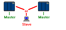
Another unique situation is the case of a terminal that seems to have two masters. What the user would see is a dumb terminal that can switch between two separate mainframe systems. If a user at a manufacturer needs to access both his system and supplier's, he may have a switch that allows him to flip between the two systems. It would seem that his terminal has two masters, but the user can only operate in onesession at a time. |
|
A session is defined as the period of time during which a user of a terminal can communicate with an interactive system. The system that controls the terminal session is referred to as the host system.
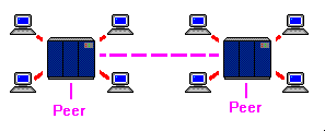
| A peer-to-peer link allows two mainframes to share data. This data can be processed by a program running on the system, or it can be passed to a slave terminal attached to the system. The two important issues to remember about the peer-to-peer link is that it is bidirectional (either system can make requests of the other) and that each system must be able to operate if the other system fails. |
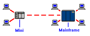
| A connection often confused with the peer-to-peer link, is the remote job entry, or RJE link. In this configuration, one system (usually a mini-computer) is designed to take input from dumb terminals, compile the data into a file, then transmit the file to the mainframe for processing. The link between the two machines is actually a master-slave link, even though there are two autonomous systems involved. In the case of an RJE, the subordinate system can not make requests of the mainframe. |
|
RJE system's are often less expensive than having dumb terminals at each warehouse connected directly to the mainframe, because the long distance telephone call between the regional warehouse and the home office is only active during updates. Furthermore, a mainframe crash at the home office does not cripple warehouses in other parts of the country. Another cost savings is realized by allowing the company to operate with a smaller mainframe. This is because many of the mundane tasks (such as user input) is offloaded to the RJE mini.
Allowing machines at different locations to collect or process information before transmitting the results to a mainframe is referred to as distributed data processing.
As corporate data processing managers began to realize that the Board Members wanted to deploy PC's, they began to wonder how these devices would fit into the big picture. By installing a communications adapter on the PC, and using special software, the PC could be made to draw data from the mainframe. At first glance this would seem to be a peer-to-peer interface, but in reality, it is only a master-slave interface. This is because the PC is said to be emulating a dumb terminal.
Emulation is when a piece of equipment imitates the actions of another.
| By using terminal emulation software, the PC can retrieve and display data from the mainframe exactly the way a dumb terminal would. The principal difference between a dumb terminal and a PC is that if the mainframe crashes, the dumb terminal becomes a paper weight, but the PC can still do word processing or spreadsheeting. This distinction earns the PC the right to be called a smart terminal. |
|
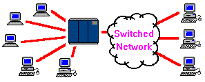
| Each store would be equipped with one PC that would act as a cash register. As sales are executed, the inventory records are updated on the PC's local storage (hard drive) and a receipt is printed. At the end of the day, the PC would connect to the mainframe and transmit the sales records. The mainframe would process the information, and provide clerks using dumb terminals with a shipping list of stock needed to replenish the stores. |
Another popular, early, deployment of the PC was the bulletin board system, or BBS.
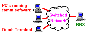
| A modem was installed on a PC which was loaded with host (mainframe emulation) software. Other PC's (or dumb terminals) could establish a 'slave' session with the 'master' BBS. In the BBS configuration, a terminal could transfer data to the BBS, where it would remain in storage, until a different terminal connected to retrieve it. As the BBS often had only one connection, only one user could connect at a time. |
|
The BBS system was the step necessary to bring about the next major advancement in telecommunications. As more users competed for the BBS connection, it was realized that what was need was a device that would be constantly available to all users. By installing a dedicated connection to each terminal rather than a switched network, users would not have to worry about contention. These systems of multiple terminals have become known as Local Area Networks, or LAN, and the BBS that serves t he LAN is referred to as the server.
| Because of this rule, a diagram of a LAN actually looks incredibly similar to that of a mainframe and dumb terminals in a master-slave relationship. Even though most equipment on the LAN are smart terminals, the relationship between the devices is still that of master-slave. Even the relationship between the PC's on the LAN is not peer-to-peer, because the PC's cannot directly communicate with each other. All messaging must go through the server. |
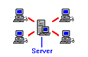
|
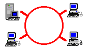
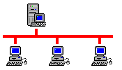
| The two systems differ in their protocols and topology, yet the principles are identical to those stated. Either system could correctly be represented as above, because all communications travel through the server. |
|
The most common modification to the original BBS, is to setup the server to act as a file server. In this configuration, the server's hard drive is divided into several 'folders'. One folder might be identified as public, to allow one PC to upload a file that could then be downloaded to another PC. Another folder might be defined as private, to allow a user the ability to quickly create a backup of important data that might be too large to fit on removable media.
Once a file server is constructed, a public directory can be created to store files that would then be accessed by the several of the PC's. A PC in receiving could download the inventory file, update it to reflect changes in stock, then upload the file back to the file server. Next, a PC in accounting could download the file, update it to reflect price changes, then upload the the file back to the file server. Each of the departments would be working with the same data and the processing of that data would be carried out by the PC as opposed to the server.
This method of using a file server was actually just another form of RJE, with a few bad side effects. Each time the data was accessed, the entire database was being shipped across the LAN. Furthermore, if receiving and accounting attempted to make their changes simultaneously, the data file could become corrupted because no single device had authority over the data.
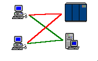
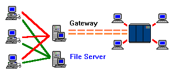
| Before we explore this problem further, we need to discuss the third most common type of server. As LAN's were deployed in offices, users began to notice that their PC's had two separate connections: one to the mainframe for terminal emulation, and the other to their server. In an effort to reduce the amount of hardware and cabling necessary to run a PC, a method was devised to deliver terminal emulation through the LAN. |
|

| By establishing a master-slave link between a mainframe and a server, a PC running emulation software can get a terminal session through the LAN. This server configuration is called a gateway server. |
|
The configuration in the previous chart is slightly deceiving. This is because a LAN with only a gateway server is of no use, as terminal emulation can be provided directly to the PC. Furthermore, if you'll remember, the reason to add the gateway server was that we already had a server connection and wanted to eliminate the terminal connection to the mainframe.
|
|
It is not unusual to inspect a LAN that has a mail, file, and gateway server on it, yet only find one server. This is because the machine is multitasking three separate software packages. Outwardly, it seems to be one machine, but it is three separate 'virtual machines.'
The solution to these problems came about with the introduction of client- server processing. The term client-server has become the PC buzzword of the 1990's. It has been over-marketed and hyped to the point that most users have little idea what it actually means. In a client-server relationship, the server retains the file, but allows it's clients (the PC's with access to the file server) to make modifications to the file. In client-server, several PC's can be processing portions of the same file, because the server is coordinating the processing.
For a LAN application to be classified as client-server, there is one hard, fast, rule that must apply. An application must be running on the PC that is transferring data to (and receiving data from) a separate but collaborative application on the server. To clarify: the applications must be designed to work together, toward a common processing goal.
The session established between the client and its partner server is similar to that of a dumb terminal and its mainframe. This, along with the fact that the server is executing a portion of the processing, causes it to be called a host server. This term helps to distinguish it from a mail or file server.
A gateway server, and its slave PC's, almost classify as client-server because each machine is running a program that handles data. The distinction is that the actual processing of the data is happening on the mainframe; the gateway server is simply a intermediate transmission device. It is important not to confuse a gateway server providing host (mainframe) access, with the host server in a client-server environment.
An example of a true client-server application would involve a user inputting parameters for a database search on a PC, which would formulate the data into a search query, and transmit the request to the host server. The request would be processed by the host server locally, and the
results would be returned to the client PC. This example differs from our earlier example, where the entire database was transmitted across the LAN, and processed on the remote PC. Client-server applications only transmit the client's queries and the server's responses.
A diagram of client-server, would look exactly like the diagram of a LAN, which makes identification of an actual client-server environment difficult. In client-server, the relationship between PC and server is no longer master-slave, because it requires that the terminal be smart enough to process the data itself. It is not peer-to-peer, because the server cannot make demands of the PC. It is not RJE, because the server retains the data. This makes client-server a new, unique, communications architecture.

|

|

|