| In all the examples of data lines given in lesson 102, the data was flowing from a host site to remote site. As the data can only go from one location to a second location at a time, it is called a point-to-point line. A switched line, such as a modem attached to a PC, is also a point-to-point line. A switched modem can (conceivably) access any other switched modem on the public telephone network, but only one at a time. As a switched line is point-to-point by its very nature, the discussion of the multi-point line is exclusive to the leased line environment.
|
|

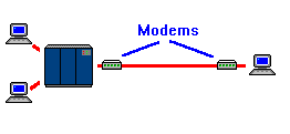
| Each PSD is equipped with a master port that always connects to the modem/DSU, and several equipment ports for the devices on the line. The device ports are sometimes referred to as shared or slave ports. The signal from the host is accepted into the main port, and repeated out the device ports. When receiving data from the line (remember that the data is originating from the host site) the PSD is broadcasting the data out to each of the ports simultaneously. |
Once the data that is received by the PSD is repeated out the device ports, it is simultaneously received by each piece of equipment. The problem now becomes one of getting the correct piece of equipment to respond. If every piece of equipment that received a transmission, responded to that transmission, the line would not function. This problem is solved by addressing each of the pieces of equipment on the line.
Addressing means that each piece of equipment on the line had a unique identifier that allows the host to choose with which device it wants to communicate. In the system known as SNA (System Network Architecture) introduced in lesson 103, the standard is to assign devices a two character Address made up of the numbers zero through nine and the letters 'A' through 'F'. This means that a device on an SNA network could have addresses such as A3, 15, 5B, CB, etc.
Now that we know that each device at the remote location is assigned a unique address, it is easier to see how order is maintained behind a PSD. Even though the PSD broadcasts the transmission to all devices connected to it, each device has enough intelligence to answer only the messages directed to it. This, again, shows the differences between a MUX and a PSD: a MUX is the intelligent device that controls access, whereas a PSD relies on the intelligence of the devices and the host.
When a device has information that it wants to send to the host, it is necessary for it to wait until the host decides to speak to it. This could present a problem if the host is involved in a lengthy download with another device sharing the same PSD. To allow every device that opportunity to transmit it's data, the host will poll each device for its status.
To poll the devices on a line is to take a role call of the equipment on the line. A polling cycle is one complete pass through the roll call of devices.
If you think of the polling cycle as if it were a radio conversation between a police dispatcher and several patrol cars, it might look something like this:
| Host sends: | Device responds: | |
| A1 do you have anything to send? | This is A1, nothing to send. | |
| A2 do you have anything to send? | This is A2, two packets to send. | |
| A3 do you have anything to send? | This is A3, nothing to send. | |
| A1 do you have anything to send? | This is A1, nothing to send. | |
| A2, send your first packet. | This is A2, first packet is: "Mary had a little lamb." | |
| A3 do you have anything to send? | This is A3, nothing to send. | |
| A1 do you have anything to send? | This is A1, nothing to send. | |
| A2, send your second packet. | This is A2, second packet is: "It's fleece was white as snow." |
|
| A3 do you have anything to send? | This is A3, nothing to send. | |
| A1 do you have anything to send? | This is A1, nothing to send. | |
| A2 do you have anything to send? | This is A2, nothing to send. | |
| A3 do you have anything to send? | This is A3, nothing to send. |
You will notice that as the host polls the devices, it does not allow the device to transmit it's data immediately. It continues through the entire polling cycle, and requests the devices packets on the next cycle, until all packets have been sent. This means that each device behind the PSD has an equal chance of sending its data. On the surface, this may seem to be exactly the trait that was said to be the multiplexer's shortcoming. The difference is that if no other device has data to send (as in the example above), the device with data gets the entire line.
A final note about polling: when a host system is utilizing a front end processor, it is the FEP, not the host, that handles the polling. The FEP handles the communications overhead of polling the devices, so the host need only communicate with devices that actually needs to sent data.
|
Now that we've discussed the workings of the port sharing device, we are prepared to move into the true nature of our lesson: the multi-point line. The PSD was originally introduced as a method of running several devices at a remote site, without having several lines. What if you only have one device at the site? Obviously, you need a point-to-point line. Now... What if you have multiple sites? Once upon a time, the answer was that you needed multiple point-to-point lines. |
|
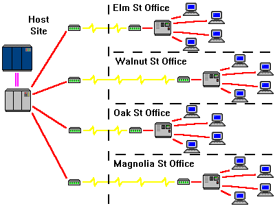
What ATT proposed was the installation of a device similar to a PSD in their central offices, with the main port connected to the host site, and the device ports connecting to the remote sites. By doing this, one modem/DSU at the host site could communicate with multiple remote facilities. This resulted in a savings in hardware, as well as fewer circuits entering the host site. Since the port sharing device was at a central office, its maintenance was the responsibility of ATT. This was another saving to the customer. The PSD in the CO was no longer thought of as a port sharing device, but was now called the bridge.
|
A multi-point circuit could be thought of as a spider, The body of the spider could symbolize the bridge. The spider's legs could symbolize the telephone lines connecting the bridge to the remote sites. These lines, by themselves, are useless without a functioning bridge. This makes them only a portion, or segment, of the whole circuit.
|

|
There is one very important thing to remember about a multi-point circuit. Data can not flow between the remote sites. All data originates at the modem/DSU on the master segment, flows to the bridge, and is broadcast to the remote segments where it drops off the circuit. It is now up to the remote device to put the data back onto the circuit, for it to flow to the bridge, and on to the master segment. No segment can communicate with any segment other than the master.
The points where data leaves the public network to enter a customer site, is sometimes called a drop.
A multi-point line functions exactly the same as a PSD. What is received on the master segment is repeated, and broadcast out all segments of the line. The bridge has no intelligence, and depends upon the devices at the remote sites to answer only when spoken to. Whatever is received from the remote segments, is transmitted back to the host site.
|
With any complex system, there is always the possibility for failure. In a mutli-point line, the most common type of failure is for the one segment to monopolize the conversation. This could be the result of a storm or auto accident tearing cables from a telephone pole that carries one of the segments. Since all data transmitted by the host is send down each segment, a short circuit could cause that data to be host's own data to be mirrored back to it.
|

|

|
When a data segment is in loopback, none of the other sites can communicate. A variation on this condition is when a device at one of the remote sites fails and sends back a constant stream of garbled data. This is called a streamer. To the other remote sites, both a streamer and loopback appear the same: they receive information, attempt to respond, but the responses are lost at the bridge.
|
|
In a loopback condition, the problem is most often in telco's cable (or a repeater in telco's network.) To stop a loopback, it is necessary for someone to go the bridge and check each segment to find one that is exactly mirroring what was shipped. Once they locate the segment that is the problem, it is removed from the bridge until it is repaired. This allows the other segments to communicate during the interim.
|

|
The outstanding success of the multi-point line has caused it spread to virtually every corner of the country, not to mention other parts of the world. As with all things telecom, its existence continued existence is proof of its value to the customer. It provides companies with a reliable method of distributing data to multiple locations without burdening the host site with a lot of hardware. Since all multi-point lines are leased lines, they provide telcos with the reoccurring fees they need to ensure their futures.

|

|

|